
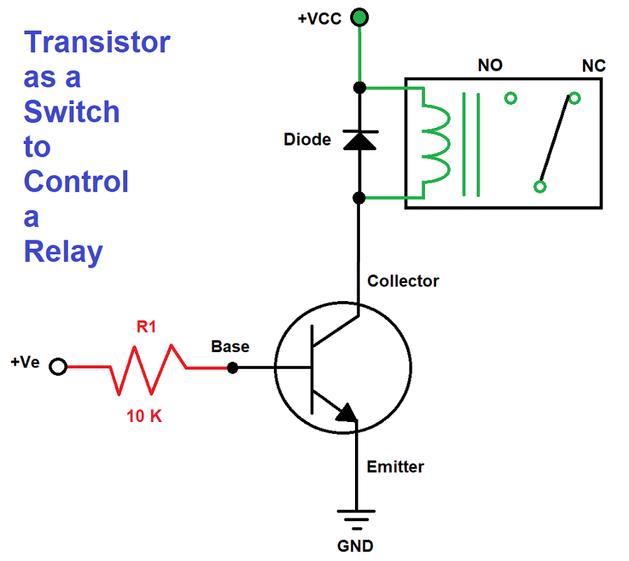
Can a Transistor be Used as a Relay Circuit Diagram The Transistor relay driver circuit helps control high-power devices using a low-power signal. It is widely used in home automation, industrial controls, and automotive electronics. Its primary function is to use a small input signal to activate a relay (5V, 6V, or 12V), which can then switch on bigger loads like motors, lights, or other high-current devices. Components List The following
How a typical transistor based relay control circuit works on appliance and HVAC control boards. Detailed information about the transistor driver circuitry, how it interfaces to a microcontroller For reasons that have little to do with the static calculations in the other answers, I would use a beefier transistor such as the 600mA 2N4401 or a MOSFET. Switching an inductive load is harder on the transistor than switching a resistive load, even with the diode. At some point the full relay coil current is flowing through the transistor for a short period of time with more than 12V across In this post we learn how to design and buld a simple transistor relay driver circuit by correctly calculating the transistor driver circuit.

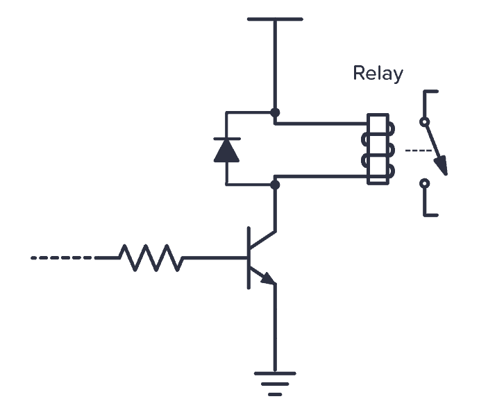
How To Make A Simple Relay Circuit using npn transistor Circuit Diagram
How to increase the gain Figure 4 is the relay driver circuit that has increasing gain up. In case that very low input current from a digital circuit. We will see that this circuit we use the transistor as a Darlington compound to replace two transistors. This video will show how to make a relay driver circuit or simple relay driver or how to use relay .It will provide the complete connection diagram and explanation of the circuit.
Circuit Design of 12V Relay Driver using Transistor as a Switch About This Video:- A relay is an electromagnetic switch operated by a relatively small electric current that can turn on or off a
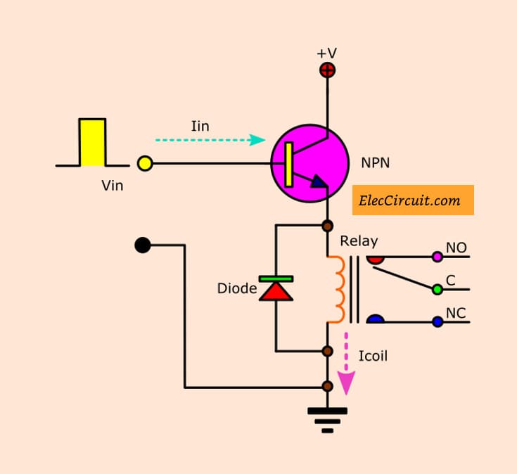
Transistor Relay driver circuit in digital Circuit Diagram
A pretty good deal for the microcontroller. How a Relay Driver Circuit Works The bipolar transistor based driver circuitry makes use of the transistor´s cutoff and saturation mode to control the relay. In other words, the transistor is used as a ¨switch¨. An electronic circuit will normally need a relay driver using a transistor circuit stage in order to converter it's low power DC switching output into a high power mains AC switching output.
