
DIY Inverter Circuit Build a Real Inverter with Feedback Design Circuit Diagram The circuit of this DIY power inverter is shown in the following figure. Working principle of this homemade inverter. After the 12V DC power is connected, the multi-vibrator that is composed of V1, V2, R1-R4, C1 and C2 starts oscillation, and the collector of V1 and V2 takes turns to output about 50Hz of square wave with positive polarity. When

There's a much easier and efficient way of making a 1 kva inverter circuit using the following 4017 PWM version circuit. Pure Sine Wave Inverter Circuit to power my house so please help me build it my 1th question im going for the LM555 where is that point show 3 to 15v dc from pin 4 of the ic lm555 going to connect second question in the

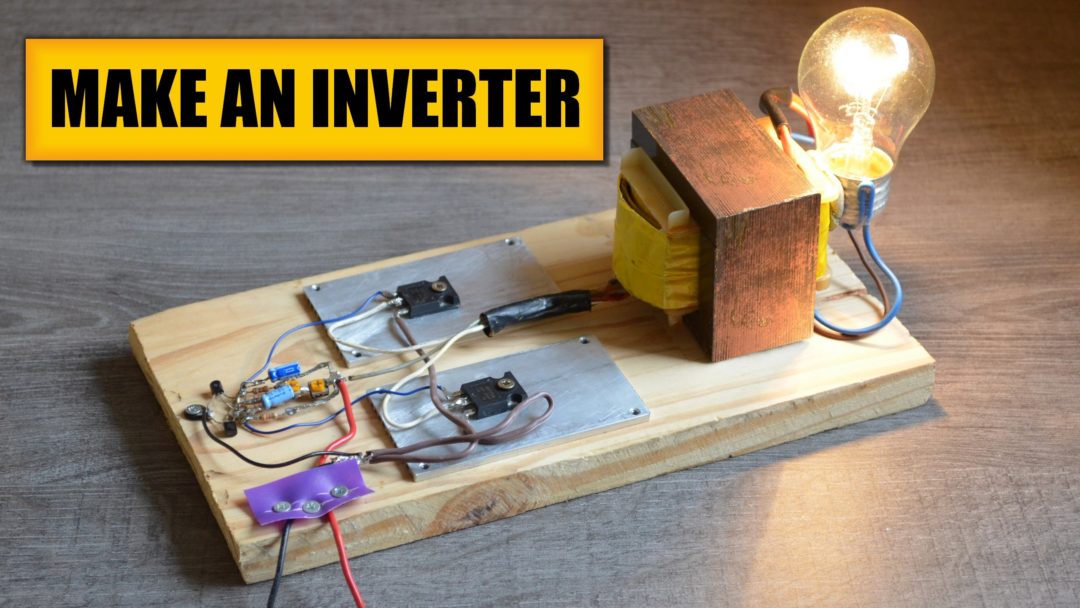
Simplest 12V to 220V DC to AC Power Inverter DIY Circuit Diagram
Fig. 1 - Circuit diagram for making Inverter at home. Theory behind the circuit. The circuit of this inverter is dissimilar when compared to the commonly used inverters as it does not have involvement of a separate oscillator circuit to power up the fitted transistors. In place of that, in our circuit, both halves of the circuit functions

Cutting PCBs is a crucial step in making a DIY inverter. Precision and accuracy are essential while using tools like a rotary tool, metal ruler, and cutting mat. and remember to include safety features like fuses and grounding. With this DIY inverter circuit, you'll be able to power appliances with ease! Building an Inverter using IC 4047
DIY SINE WAVE INVERTER WITH IC NE555, MOSFET IRFZ44N ... Circuit Diagram
The maximum power of this inverter depends on the size of the transformer and the input power supply. The frequency of this circuit is around 60 to 70Hz and the efficiency of this circuit is around 63%. So guys that is all for this project. Thankyou! Watch Full Step by Step video --> Full Video. Check out our Youtube Channel -->creativElectron7M
