
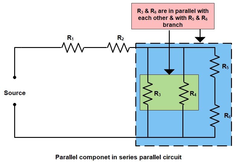
Practical Of Series And Parallel Circuits Circuit Diagram Two fundamental ways to connect resistors are in series and in parallel. Understanding the differences between resistors in parallel vs series is crucial for designing and analyzing electronic circuits. In this article, we will delve into the principles, formulas, and applications of resistors in parallel and series configurations. The shortcut is like the path of a parallel circuit. Runners could take many shortcuts across the field—at the 10-, 30-, 70-, and 90-yard lines, for example—illustrating the way multiple parallel circuits may be added to an electric circuit. Series and parallel configurations may work together. Many real-world systems combine series and parallel configurations to achieve specific goals, such as balancing resistance and current. These are called series-parallel circuits. Example: A Mixed Circuit. A circuit consists of: A 12V battery. Resistor R 1 = 4 Ω in series. Two resistors, R 2 = 6 Ω and R 3 = 3 Ω, connected in parallel.

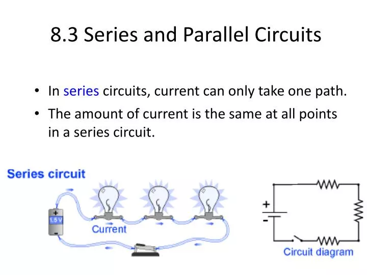
Series and parallel circuits are fundamental to understanding electronics and designing efficient electrical systems. These configurations define how components like resistors, capacitors, and diodes are connected in a circuit, influencing the overall behavior of the system. Understanding Series Circuits. In a series circuit, components are

Resistors In Parallel Vs Series Circuit Diagram
By understanding the principles of series and parallel wiring, designers and engineers can create electrical systems that are safe, efficient, and effective. Whether it's a simple circuit or a complex system, the proper wiring configuration can make all the difference in ensuring reliable operation and minimizing power losses.
Understanding series and parallel circuits is fundamental in the field of circuit theory, forming the basis for more complex electrical circuit analysis and design. By understanding how to work with both series and parallel configurations, engineers can develop efficient, reliable, and innovative electrical systems. Related Posts: AC and DC Parallel vs. Series Circuits Understanding the Difference with a Practical Example . Electrical circuits can be connected in different ways, and the two most common methods are parallel and series configurations. The choice between these two can affect how devices behave in terms of brightness, functionality, and power consumption.
Series and parallel circuits Circuit Diagram
Resistors in series and parallel configurations affect circuit resistance, voltage, and current. Series resistors increase total resistance, while parallel resistors decrease it, using Ohm's law and Kirchhoff's laws for calculation. Resistors are fundamental components in electronic circuits, and understanding how they behave in different
