Solved 510 Design an op ampbased highpass filter with a Circuit Diagram Step-by-step design of Active low pass filter using Op Amplifier. So as you can see, there a number of factors that go into creating a low pass filter with an op amp. If you are dealing with high-frequency signals, then it's best to use a much higher-speed op amp than the LM741. For relatively low frequencies, it should suffice. And this is how a low pass filter circuit can be an op amp. Related Resources 1. To design a First Order Low Pass OR a High Pass Filter using an Op-Amp and a designated capacitor as the frequency determining component. 2. Build the low-pass or high-pass filter of your design and check its frequency response. Drive the circuit with a sine wave and record input (constant) and output voltage for different frequencies.
Hi, thanks for watching our video about active filters! In this video we'll walk you through:- How to design, simulate and build active opamp filters- Using
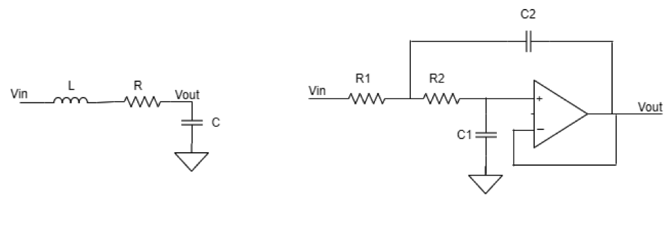
Active Low Pass Filter Circuit Diagram
This type of filter is also known as a single-pole RC filter, since it involves only one reactive component. The typical configuration of a first-order low-pass filter with an operational amplifier is called a low-pass RC filter. In RC low pass filter, the capacitor is connected between the inverting input of the op amp and its output. Active Low-Pass Filter Design Jim Karki AAP Precision Analog ABSTRACT This report focuses on active low-pass filter design using operational amplifiers. Low-pass filters are commonly used to implement anti-aliasing filters in data acquisition systems. Design of second-order filters is the main topic of consideration. This circuit is an op-amp-RC resonator: it produces resonance using only resistance, capacitance, and amplification. We could use this circuit to replace the inductor in a second-order RLC (resistor-inductor-capacitor) filter, but instead, we'll look at a simpler and more compact topology known as the Sallen-Key filter. Second-Order Active
Circuit diagrams and their building blocks, such as low-pass filters and op amps, may sound complex, but the basics are easy to understand and apply. Op amps are the backbone of many audio circuits, and low-pass filters are one of the most common op amp applications.